Hi All,
As we’ve learnt about channel formation and MOSFET working. We’ll now move ahead with a very important concept of Drain current and its behavior.
Note: This explanation primarily focuses on modern short-channel MOSFETs used in today’s technologies. Some behaviors differ slightly from the classical long-channel MOSFET model taught in textbooks.
And we’ll also see a very important interview Question : THE GRAPHS 💥
Linear Region.
Here you need to first learn what’s drift velocity which we will directly associate with the linearity of the MOSFET.
When we increase the VDS, we’ll first see the Id is also increasing with it.
Analogy : When you turn up the tap more (Increase of VDS voltage ), more water will from from the tube (More Id i.e. drain current)
Real : Similarly in real case, In an NMOS transistor, electrons move from source to drain when you apply a voltage across it. They move with some average speed because they keep bumping into silicon atoms. This average speed of the electrons along the channel is called the drift velocity.
The higher the drain–source voltage (VDS), the stronger the electric field, and the faster the electrons drift. So at first, drift velocity increases almost linearly with the electric field.
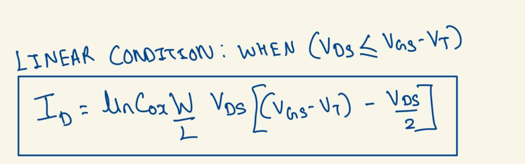
Drain Current equation (LINEAR REGION):
Saturation Region.
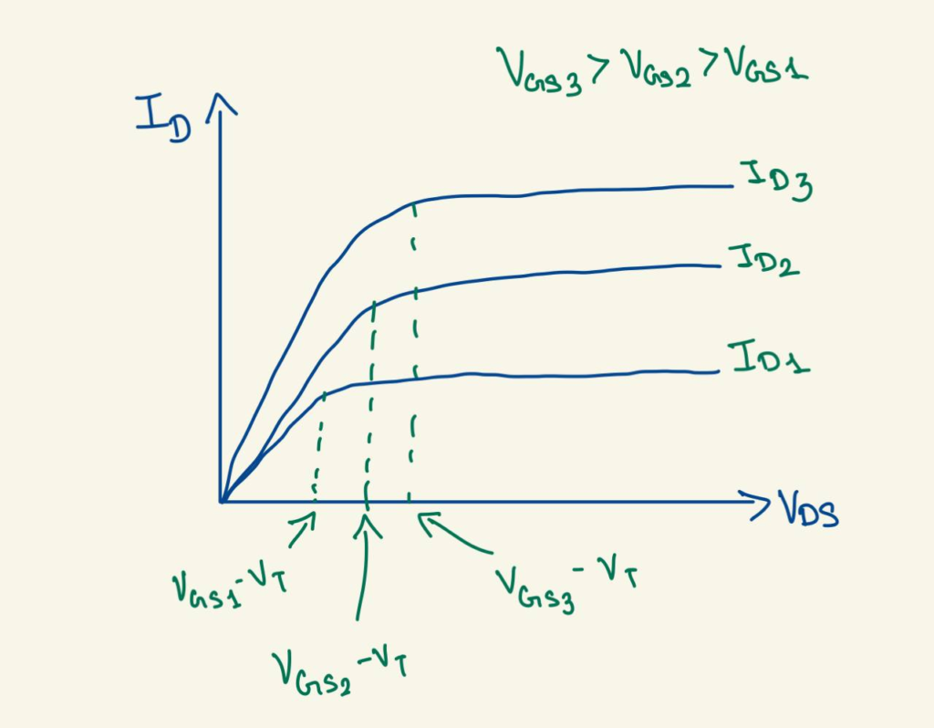
Here even though you increase Vds more the Id will not increase after a certain point.
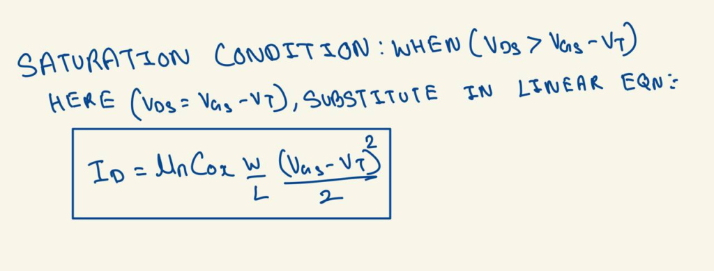
As Vds increases, the voltage drop along the channel also increases. The channel gradually becomes thinner near the drain because the gate-to-channel voltage is smaller there. When Vds = Vgs- Vt, the channel at the drain end disappears. This is called pinch-off. Beyond this point, increasing Vds only extends the pinch-off region slightly instead of creating a wider conducting channel, so the drain current Id remains almost constant.
Analogy : When you keep on increasing the tap but the tube width(channel width) will try to stop you from increasing the water flow after a certain point.
Real: But electrons can’t keep getting faster forever. At very high electric fields, they keep bumping up frequently with the silicon atoms that their velocity stops increasing. They reach a maximum constant speed called the saturation velocity. In modern short-channel MOSFETs, velocity saturation also plays an important role. We’ll study this short-channel effect in detail in a future blog.
The condition for it is Vds > Vgs-Vt
Drain Current equation (SATURATION REGION):
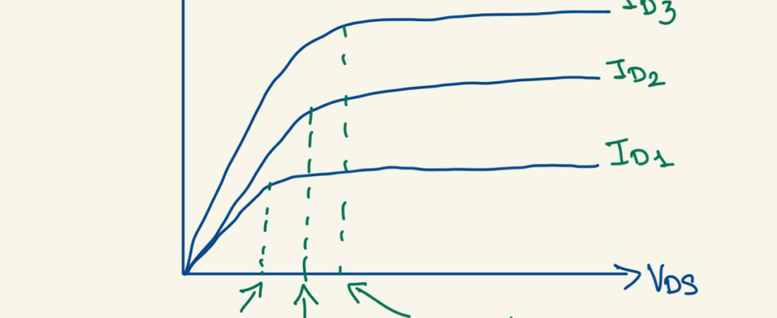
Here’s the graph of Id vs Vds:
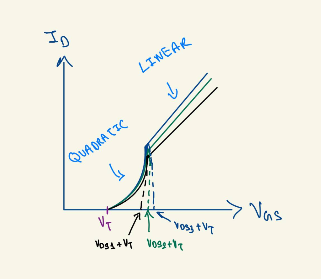
Id vs Vgs
In this graph first there comes Vt(Threshold voltage) which enables the current to flow, so that’s where the graph starts.
Initially, the drain current increases approximately quadratically with Vgs. In modern short-channel MOSFETs, as the electric field becomes very high, electrons reach velocity saturation. Beyond this point, further increases in Vgs mainly increase the inversion charge rather than the electron velocity, causing Id to increase almost linearly with Vgs.
Analogy: Think of Vds as the water pressure, which is already available. Initially, there is no pipe, so no water flows.
As soon as Vgs crosses the threshold, a very thin pipe starts forming. Even a small increase in its width allows much more water to pass, so the flow increases rapidly.
As you continue increasing Vgs, the pipe becomes wider and wider. However, after a certain point, simply making the pipe wider doesn’t increase the flow as dramatically because the water is already moving nearly as fast as it can.
Here’s the graph of Id vs Vgs:
Hope you enjoyed reading the analogies and understood the concept. Happy Learning 😊
For Feedback and more updates, join this Telegram channel: https://t.me/thesiliconpath